
A jersey or memorabilia frame may be visually appropriate, securely fixed and still create a circulation-path concern because its front edge projects too far from the wall. For U.S. projects, the ADA Standards address wall-mounted objects whose leading edges fall within a defined height zone. Product depth, mounting method, wall conditions and location therefore need to be reviewed together.
This guide helps hotels, schools, universities, healthcare facilities, clubs, civic venues, architects and programme buyers request useful dimensional and installation evidence from a display-frame supplier. It does not decide whether the ADA applies to a particular site, approve an installation, select wall fixings or replace the architect, accessibility specialist, code official, structural engineer, facilities manager or local counsel.
Understand the hazard the rule addresses
The U.S. Access Board explains that protruding-object requirements help prevent hazards to people with vision impairments who travel along circulation paths and use walls as wayfinding cues. The rules are not limited to an accessible route. Interior and exterior walks, hallways, courtyards, ramps, landings and circulation paths within rooms can be relevant.
A deep frame is one of many possible wall-mounted objects. The review is about the installed geometry in a circulation path, not whether the object is decorative, custom made or sold as furniture. Do not assume a lobby display is outside the issue because people can walk around it. Ask the project accessibility professional to map the circulation path and adopted requirements.
Know the federal dimensional trigger
Section 307.2 of the ADA Standards states that objects with leading edges more than 27 inches and not more than 80 inches above the finish floor or ground may protrude a maximum of 4 inches horizontally into the circulation path. The Access Board guide illustrates the rule from the wall surface and explains related conditions. These figures are a starting point for professional review, not a complete site approval.
Objects whose leading edges are within cane sweep, at 27 inches maximum, or above the headroom zone can be treated differently under the federal provision, but other requirements still matter. Accessible-route width, headroom, operable parts, local code, fire rules and site-specific risks do not disappear. Do not reposition a frame merely to escape one dimensional trigger without a coordinated design review.
Measure the leading edge in the installed condition
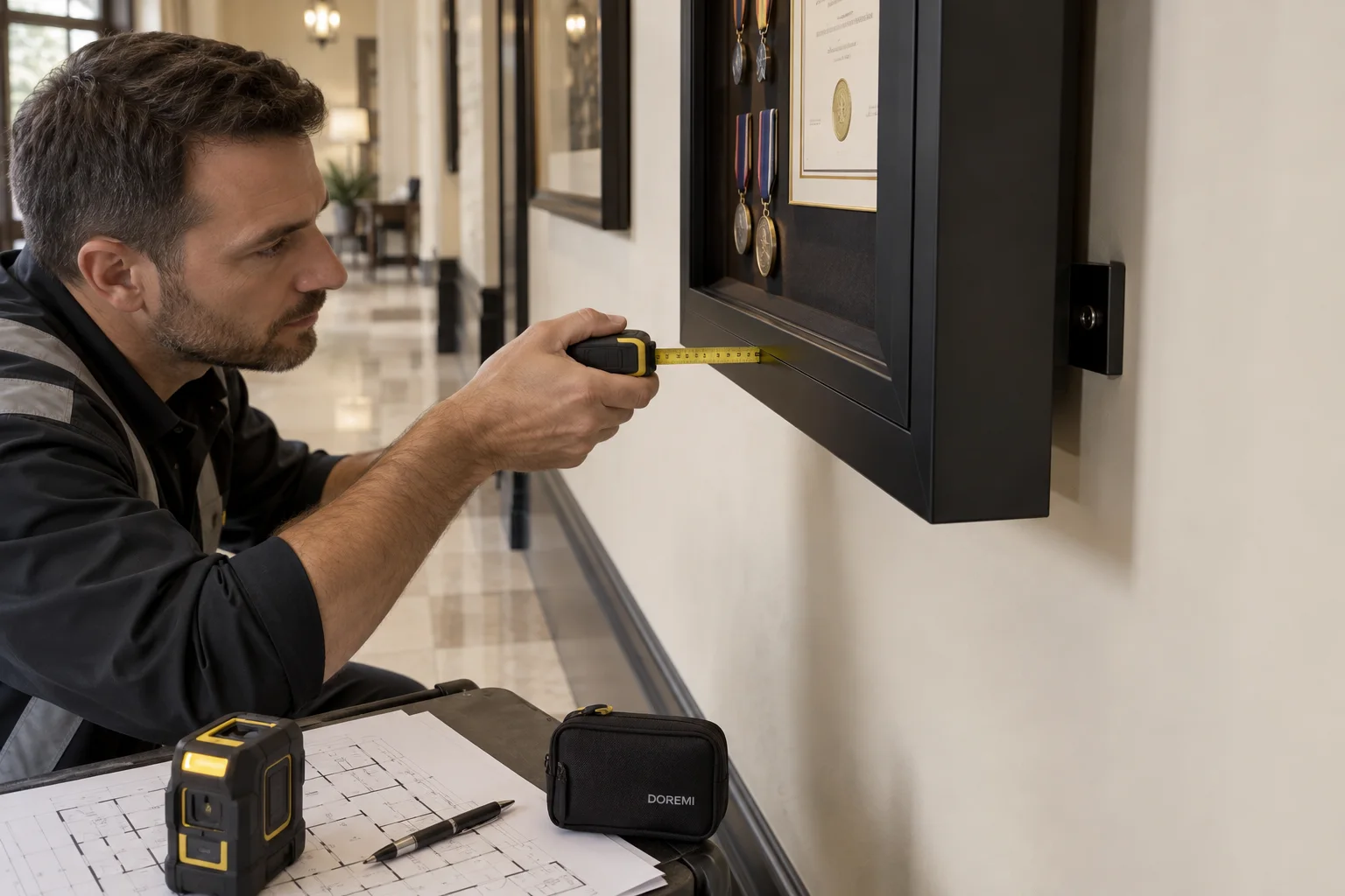
The product catalogue depth is not necessarily the installed projection. Add stand-offs, cleats, brackets, security hardware, cable channels, wall irregularities and any openable element that remains in the circulation path. Establish the wall or fixed-element reference from which the project professional wants the measurement taken. Record the greatest leading edge, not a convenient recessed portion of the profile.
Measure after the final hardware is engaged and the frame contains its intended object, glazing and backing. A heavy jersey or multi-medal display can sit differently from an empty shell. Capture a side photograph with a rigid reference and a dimensioned sketch. A tape-measure photo is supporting evidence; the released installation drawing should state the method and responsibility.
Record the vertical zone accurately
Measure the height of the relevant leading edge above the finished floor, not above skirting, furniture or an unfinished construction datum. If the frame has a bevel, shelf, plaque, lock or projecting trim, identify which feature creates the leading edge. Floors can slope, and a long display can cross more than one condition. The site team should select the controlling measurement points.
Keep mounting height separate from artwork eye level. A curator may prefer a visual centreline, while accessibility and facilities teams need bottom, top and leading-edge heights. Put all three on the elevation. If furniture or a detectable element is intended to change the condition, show its fixed dimensions and location rather than relying on a movable table or planter in a photograph.
Map circulation before selecting a frame depth
Ask for a plan that shows wall, circulation path, doors, turns, queuing, seating, drinking fountains, controls and adjacent projections. A display in a private office may be reviewed differently from the same display beside a public lift or along a school corridor. The Access Board notes that protruding-object provisions apply broadly to circulation paths, including spaces not limited to designated accessible routes.
Coordinate early with the architect or accessibility specialist. If the location cannot accept the proposed depth, options may include a shallower construction, recess, different wall, layout change or an appropriate fixed detectable element designed by the project team. The frame supplier can provide product geometry; the building professionals determine which solution works with the whole site.
Design depth from the displayed object outward
A deep jersey frame needs enough internal clearance for the garment, support, spacers, plaque and glazing, plus the structural profile and rear hardware. Build a section from the actual object rather than starting with an arbitrary outside depth. Folding or support changes can sometimes reduce depth, but should not create textile stress or push objects against glazing.
Identify fixed requirements and opportunities. A medal boss, thick folded sleeve or stand-off plaque may control the case. Moving a plaque beside rather than in front of a jersey can reduce the deepest layer. Ask the supplier for two or three section options with the same visible story, then let the buyer compare appearance, serviceability, cost and site projection.
Include doors and service positions
Some display frames hinge open, slide forward or lift from a cleat. The closed position is not the only operational geometry. Record the opening arc, temporary working zone, panel support and whether service can occur while the building remains occupied. An open door can create a short-term hazard even when the closed case meets the intended projection.
Assign a service procedure: time, barriers, tools, staff and route closure if needed. Public users should not be expected to open a deep wall case in a busy corridor. For frequently changed certificates or records, consider a mechanism and location that supports safe access. The supplier should demonstrate opening on a production-equivalent sample; facilities should approve the operational plan.
Do not confuse projection with structural safety
A four-inch projection check does not show that a wall can carry the frame. Completed mass, centre of gravity, hardware, fastener spacing, substrate, backing, dynamic loading, tampering and seismic requirements may influence engineering. Give the structural or facilities professional a finished weight and dimensioned mounting drawing, including any object and glazing.
Do not publish a universal screw, anchor or load rating without evidence for the exact assembly and wall. If fixings are excluded because site substrates vary, say so clearly. The installer should identify the wall construction, concealed services and required attachment system. High, heavy or public-area frames may require engineer review and professional installation independent of accessibility checks.
Request a useful supplier drawing
The handover drawing should show outside width and height, maximum closed projection, internal usable depth, frame profile, glazing, backing, cleat or bracket, stand-off, fastener locations, completed mass, centreline, bottom and top heights for the proposed installation, service movement and any separate protruding plaque or control. Use one unit system consistently and include revision status.
Ask the supplier to state which values are product dimensions and which depend on the site. A factory can measure the frame and supplied bracket; it cannot confirm finished floor height, wall flatness or local substrate remotely. Keep assumptions visible. An attractive front rendering without a side section is not enough for facilities coordination.
Use a full-scale mock-up for deep or repeated installations
A cardboard, foam or timber depth mock-up can reveal conflicts before finished frames are ordered. Match the maximum outside geometry and proposed mounting height, then place it on the actual wall or a dimensionally accurate site sample. Have accessibility, facilities, curatorial and operational representatives review the location together.
Label the mock-up as a geometry study, not a structural installation. Observe circulation, door movements, cleaning equipment, queuing and sightlines. For multiple frames, include the worst-case object and spacing. Record comments on a marked plan and update the supplier drawing. A photograph of people passing the mock-up can help discussion but does not substitute for dimensional assessment.

Write instructions for the actual installer
The U.S. Consumer Product Safety Commission’s general guidance on product instructions emphasises understandable task order, consistent terminology, useful illustrations and risk communication. Apply those principles to the frame: inventory parts, identify completed weight, show orientation, mark attachment points, explain lifting and engagement, and distinguish supplied hardware from site-selected fixings.
Warnings should follow the project risk assessment, not generic label habits. Describe the hazard and avoidance action in language suitable for the destination. Use diagrams that match the production model. If professional installation or temporary corridor control is required, state it. Have qualified legal and technical reviewers approve safety language.
Verify the installation instead of the carton
Create a site closeout record for frame model and revision, wall location, finished floor reference, final projection, leading-edge height, outside dimensions, completed weight, selected fixings, installer, date and photographs. Confirm that the product sits fully on the bracket and that rear stand-offs or cables have not increased depth.
Review adjacent objects and route width after installation. A compliant product drawing can be defeated by an unexpected wall feature, sign, bench or later furniture change. The responsible project professional should determine acceptance. DOREMI or another supplier can support the product record, but should not sign a building-level accessibility approval outside its role.
Plan inspection and maintenance
Periodic facilities checks can look for looseness, tilt, impact damage, opened backs, displaced spacers or furniture changes around the display. If the case must be opened, verify that it returns to the approved closed position. Record any replacement bracket or stand-off, because apparently minor hardware changes can alter projection or structural behaviour.
Make complaints and near misses traceable to the exact location and model. A repeated contact issue may indicate circulation behaviour that the original drawing did not capture. Facilities, accessibility and safety owners should decide corrective action. Moving a frame, adding a barrier or changing mounting height can introduce new requirements and should be re-reviewed.
Control variants and reorders
A programme may share one visual front while jersey thickness, plaques, lighting, locks or mounting hardware change by site. Build a variant table with maximum projection and mass for each configuration. Do not let the shallowest sample represent a deeper production variant. The installation drawing and carton label should identify the applicable model.
On reorder, require disclosure of profile, glazing, backing, hardware and stand-off changes. A supplier substitution that adds only a few millimetres can matter near a project limit. Route changes through facilities and design review before shipment. Archive the final installed record so future renovations do not rely on memory.
Facilities buyer checklist
- Applicable federal, state, local and owner requirements assigned for review
- Circulation path and finished floor reference mapped by the project team
- Leading-edge height and maximum installed projection shown
- Actual object, backing, glazing and hardware included in dimensions and weight
- Service opening and temporary work zone documented
- Wall substrate and site-selected fixings reviewed by qualified professionals
- Supplier drawing separates product data from site assumptions
- Full-scale mock-up reviewed where depth or repetition creates risk
- Instructions match the production model and installation sequence
- Final site measurements and photographs retained
- Periodic inspection and incident route assigned
- Variant and reorder changes trigger renewed coordination
Experience scope and project limits
Editorial review: Jessica, Founder & Project Advisor at DOREMI Display. Updated 19 September 2026. Jessica’s practical scope covers B2B display-frame briefs, dimensioned product handover, sample coordination, manufacturing communication, packaging and buyer records. She is not presented as an architect, accessibility specialist, code official, structural engineer, licensed installer, lawyer or government authority.
This guide is educational supplier-preparation material, not legal advice, a site survey, engineering design or ADA certification. Applicability, measurements, circulation paths, mounting height, wall structure, fixings, warnings and final acceptance must be decided for the actual project by qualified responsible parties under the rules adopted in that jurisdiction.